This guide is based on information originally found here:
http://jbx9.free.fr/...ex.php?page=OPS
The topic was discussed, and a solution found here:
http://www.carpe-tdm...showtopic=16514
Without the skills and determination of leehenty, I would still be searching for the oil pressure switch / adapter to be able to do this - thanks Lee
Installation procedure:
1. Remove the top fairing from the bike (The Haynes Manual details how to do this)
2. Remove the nuts holding the instrument cluster on and the speedo cable (circled). Also disconnect the two black wiring plugs (also circled)
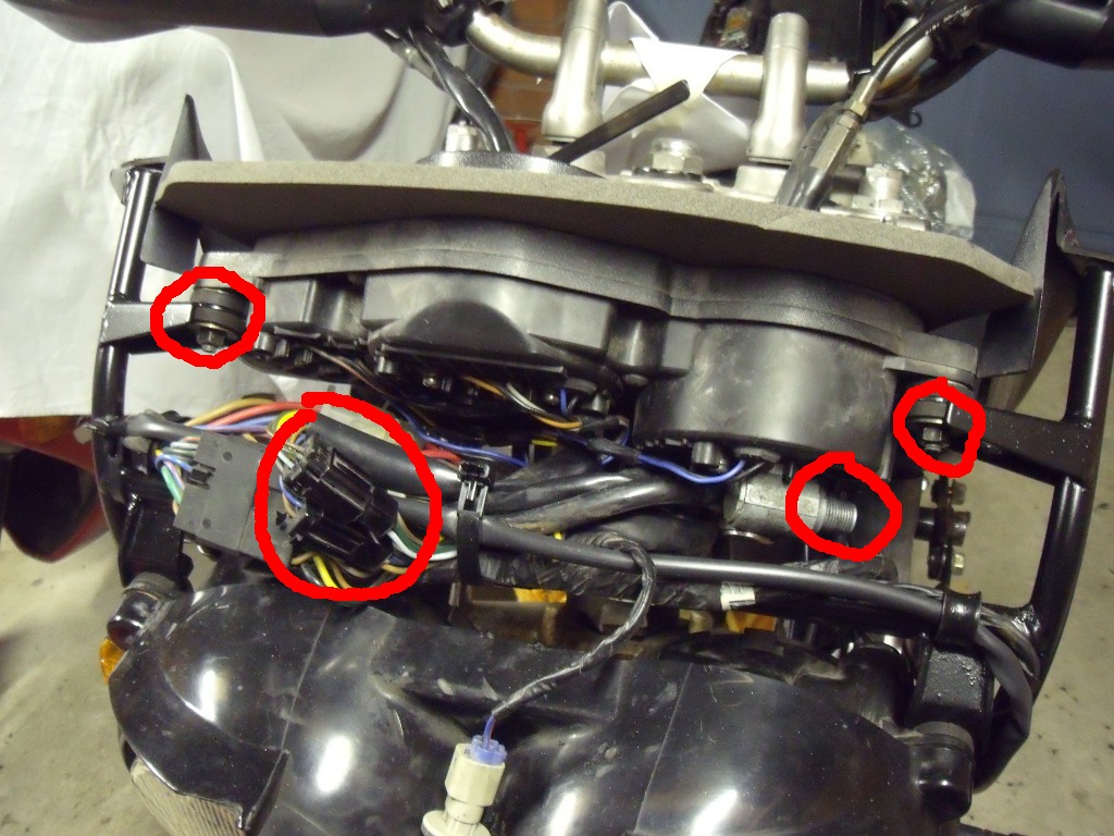

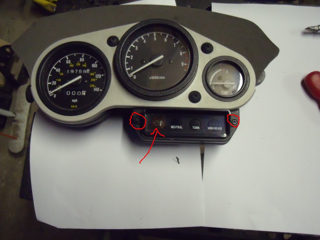
3. Remove the five screws holding the instrument cluster together (note the one at the bottom right is a smaller screw). The arrow in this photo shows the spare warning lamp socket.


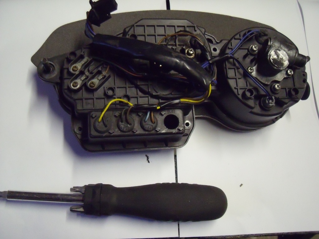
4. Carefully separate the two halves of the instrument cluster, take care not to put greasy fingerprints on the instrument faces. The spare warning light socket is blanked off (indicated in photo)
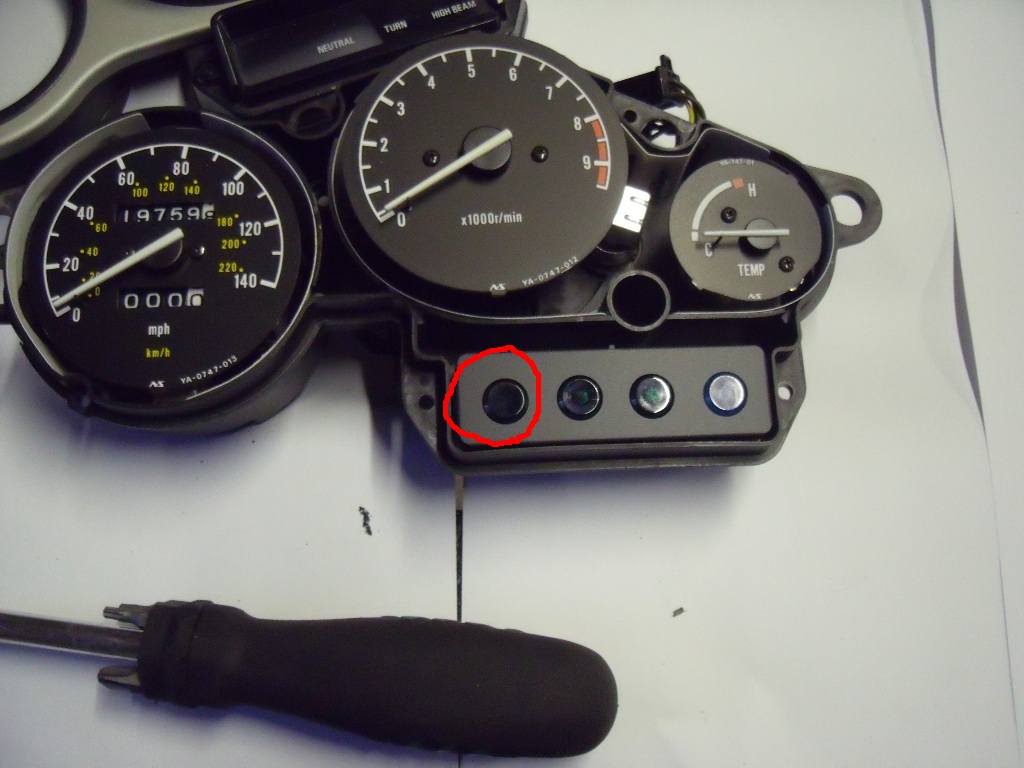
5. Carefully knock the blanking plug out from the rear of the cluster.

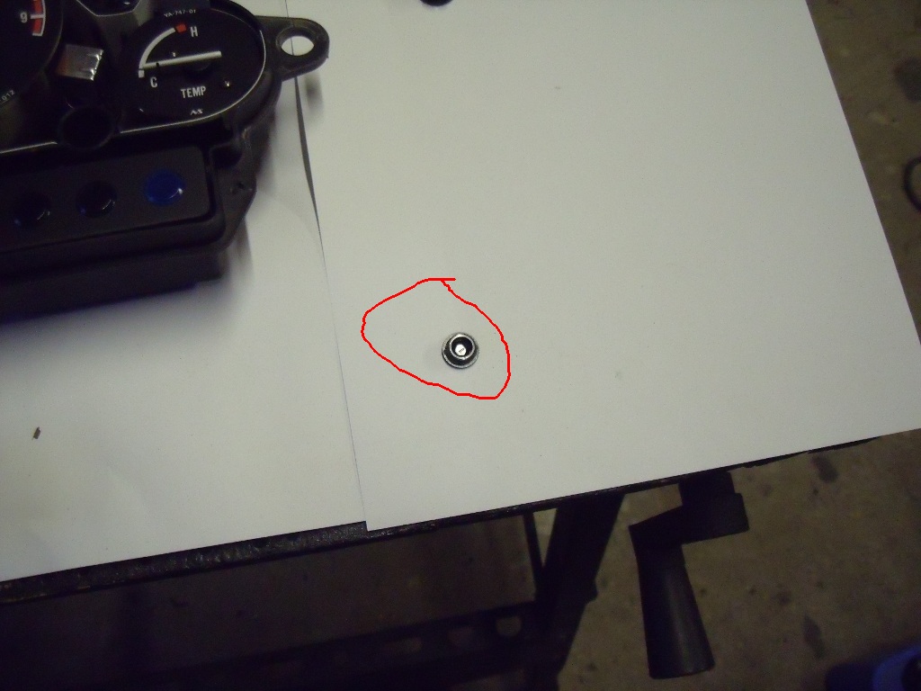
6. The hole you are left with is 10mm in diameter, if you have a warning lamp or filter to fit this, simply push it in, using a little glue if necessary.
7. If you need to use a bigger warning lamp, you may need to enlarge the hole (I used one of these)

from here : http://www.vehicle-w...rninglights.php
The above lamp is 12mm so I needed to enlarge the hole to fit it.
8. Carefully knock the light panel out from the rear of the unit (use a piece of wooden dowel or something else soft).

Enlarge the hole, the metal is fairly thin and delicate, I just used a 12mm drill bit and twisted it through by hand. The resulting hole was a little
rough but, once the lamp was fitted this didn't show.
9. Fit the lamp / filter using a little glue if necessary
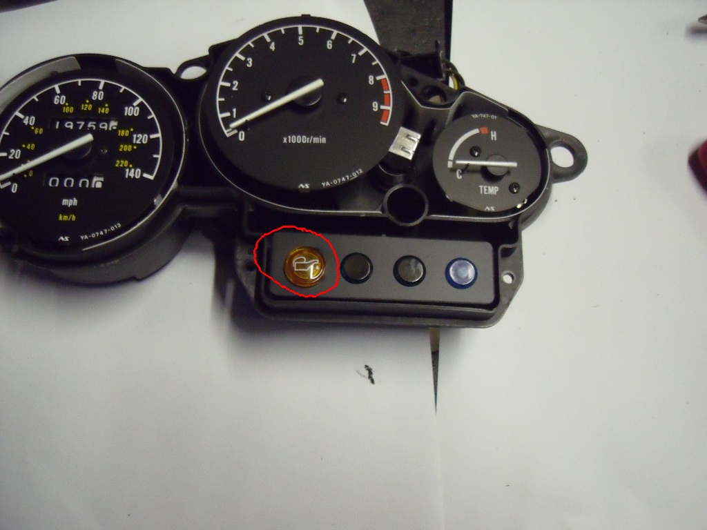
10. Put the instrument cluster back together (note the two bolts circled on this photo are fake, don't try to undo them you'll just make a mess!)
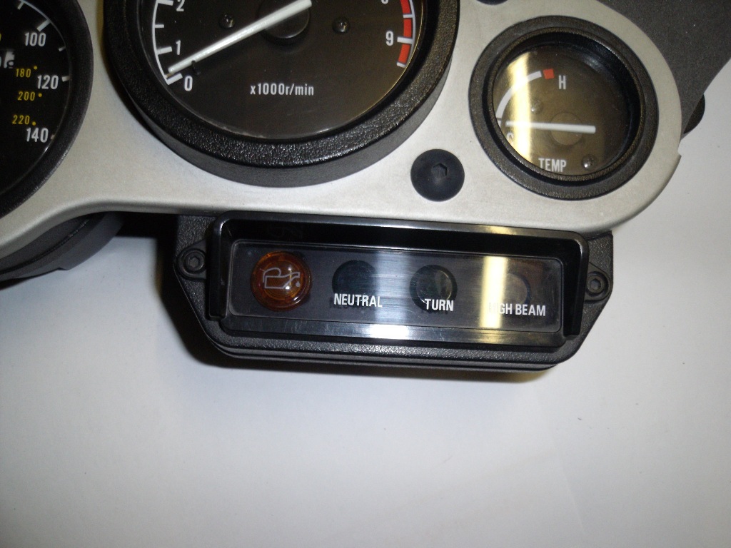
11. Looks pretty good
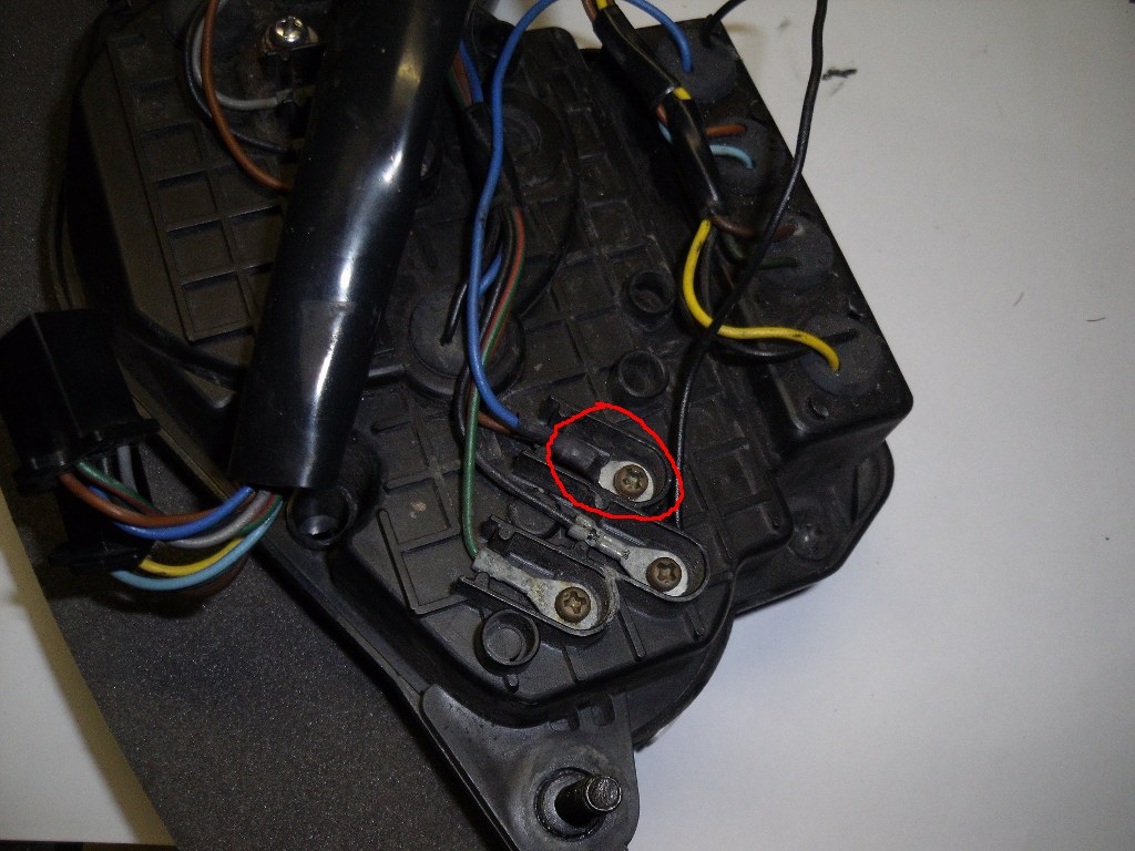
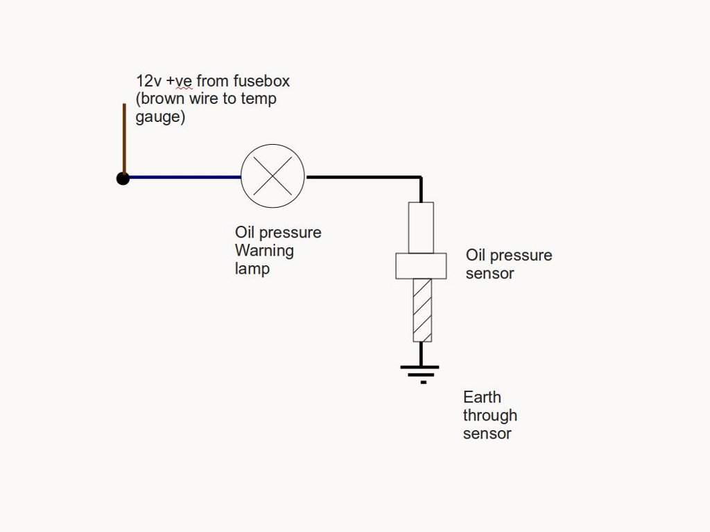
12. Wiring time, the brown wire with the ring connector circled is going to provide a 12 v +ve feed for our oil pressure warning lamp. We also need to connect a bulb or wiring to the new lamp and seal it from the elements.
13. I had a spare bulb holder (seen here fitted with a LED wedge bulb)

14. Here we see the brown ring terminal on the temp gauge disconnected ready to be connected along with the blue wire to the 12v +ve supply. The bulb holder is now fitted to the cluster.

15. Crimp a small ring terminal to your +ve wire (blue in this case), solder it too if you want.
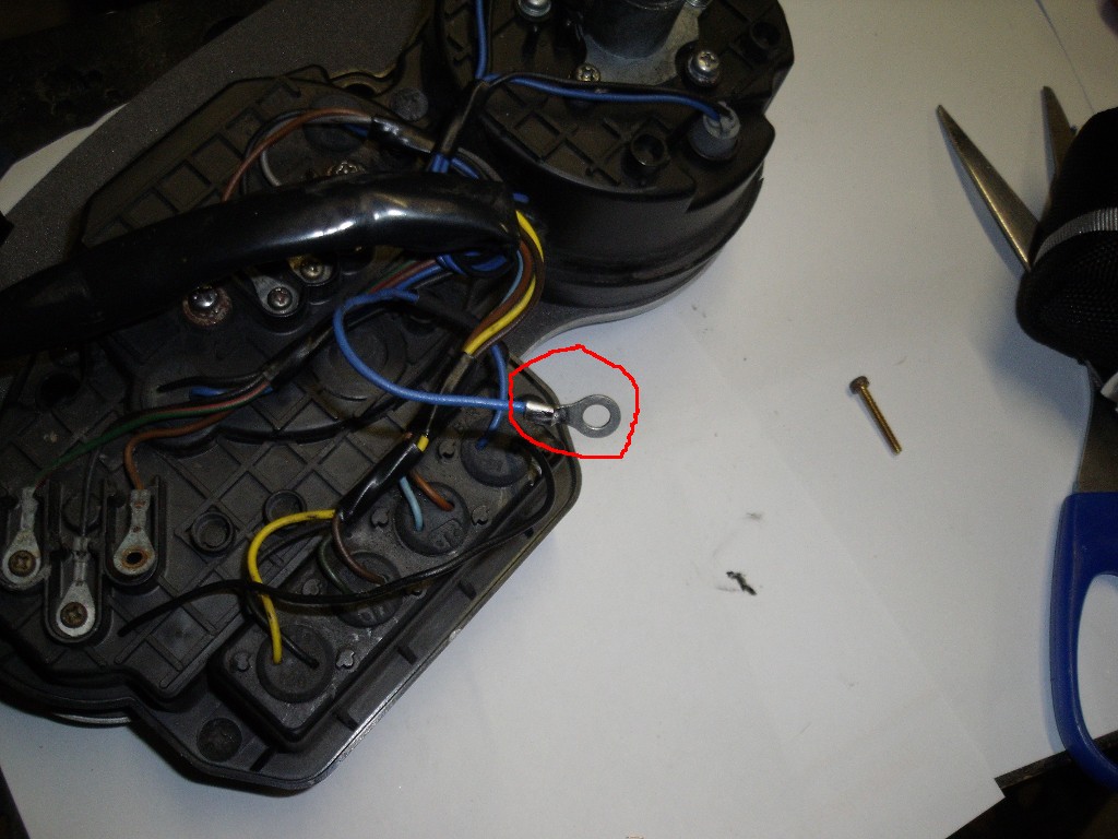
I added some heat shrink to the bottom of the ring terminal too.
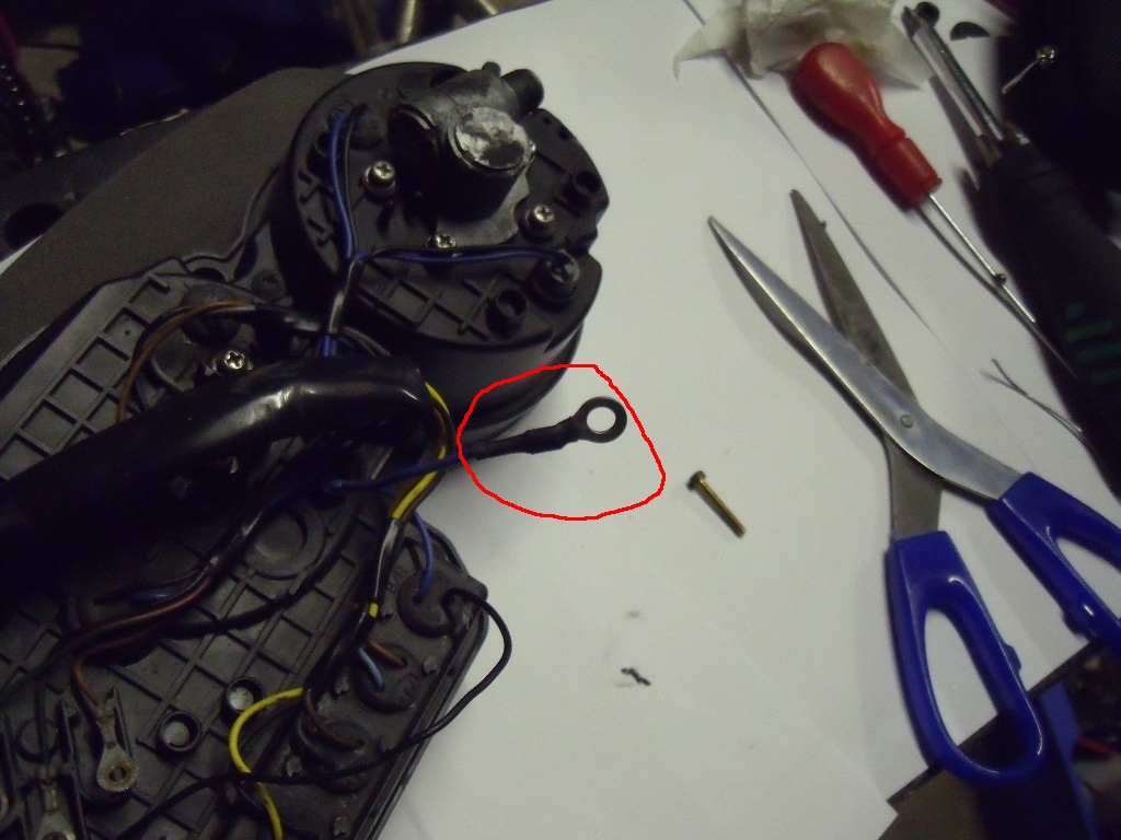
16. Connect the new ring terminal and the old brown one together and screw them back in the original position (clean the old one up if necessary)
17. Solder a length of wire to the -ve wire on your blub holder (black one a few photos back) and feed the wire through the PVC sleeve on the back of the cluster. Crimp / solder some sort of connector with a weather proof cover on the end. This will allow you to completely remove the instrument cluster at a later date if you need to. Also tidy the wiring up with cable ties or tape on the back of the cluster.
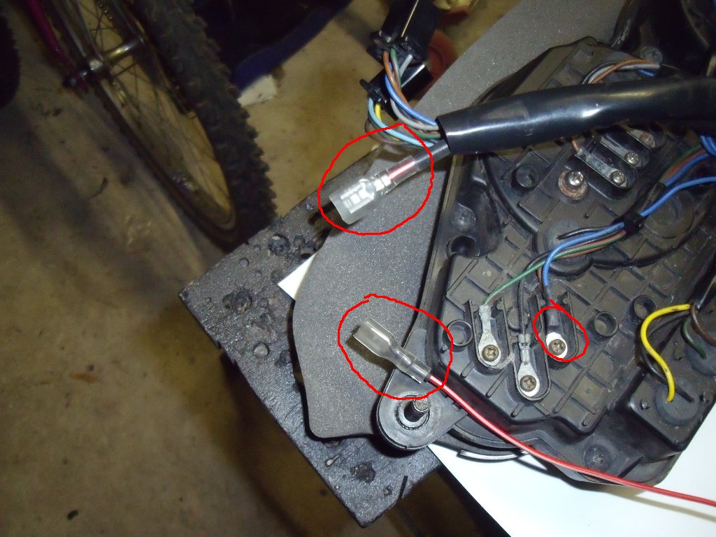
18. All we need to do now is run a length of wire to the location of the oil pressure sensor on the left had side of the engine. Crimp / solder another connector with a weather proof cover on it to this wire and connect it to the one you just did.

19. Reinstall the instrument cluster on the bike, with the two mounting nuts. Connect the two black connectors and the speed cable. Also tidy the wiring up

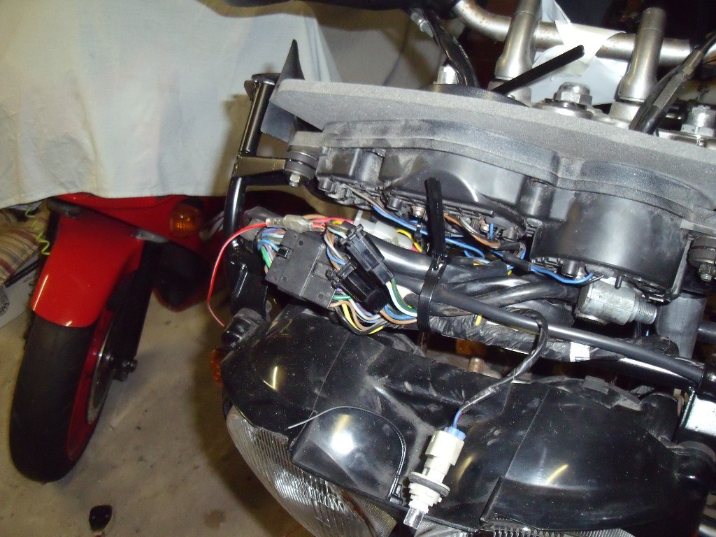
20. The new wire is going to need protecting, I covered it in PVC wiring protection, but spiral wrap or braided wiring covering would both work. Secure the new wire to the existing loom with cable ties or tape.
These are available from here:
http://www.vehicle-w...ng/sleeving.php

21. Secure the new wire to the existing loom with cable ties or tape, keep this as tidy as possible
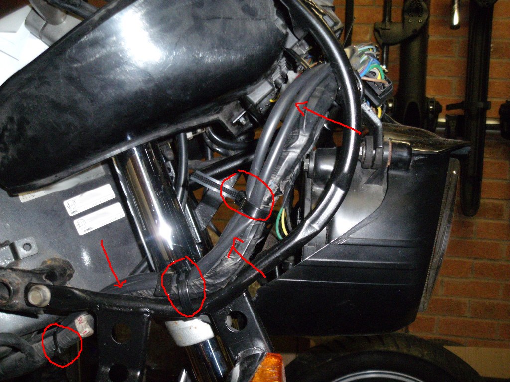

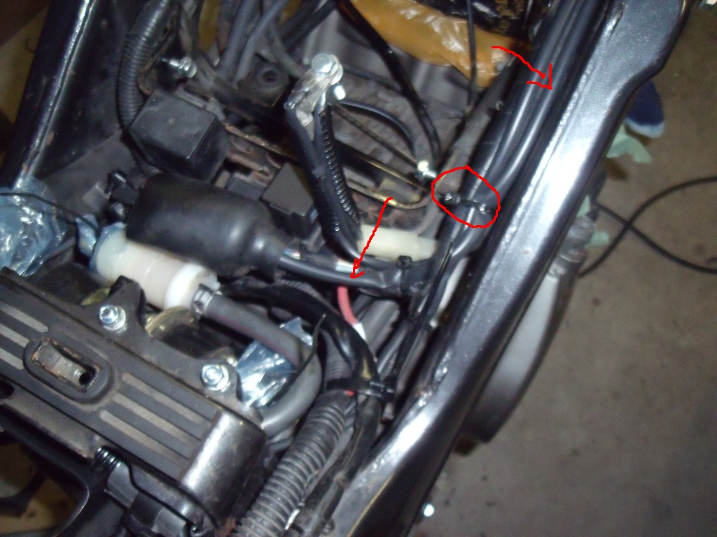
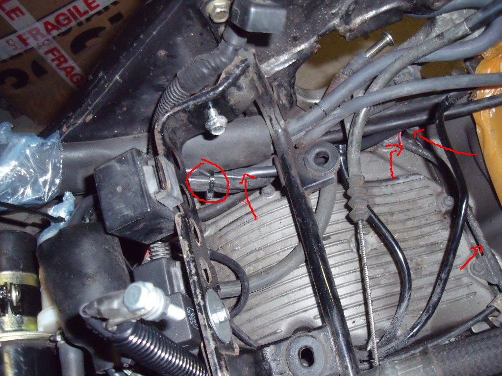
22. The wire routed to the left hand side of the engine, the oil pressure switch will be installed in place of the banjo bolt indicated.
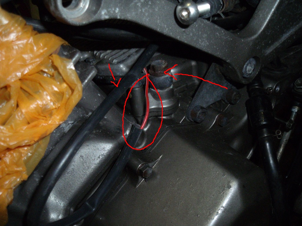
23. Crimp / solder a ring terminal to the end of the wire
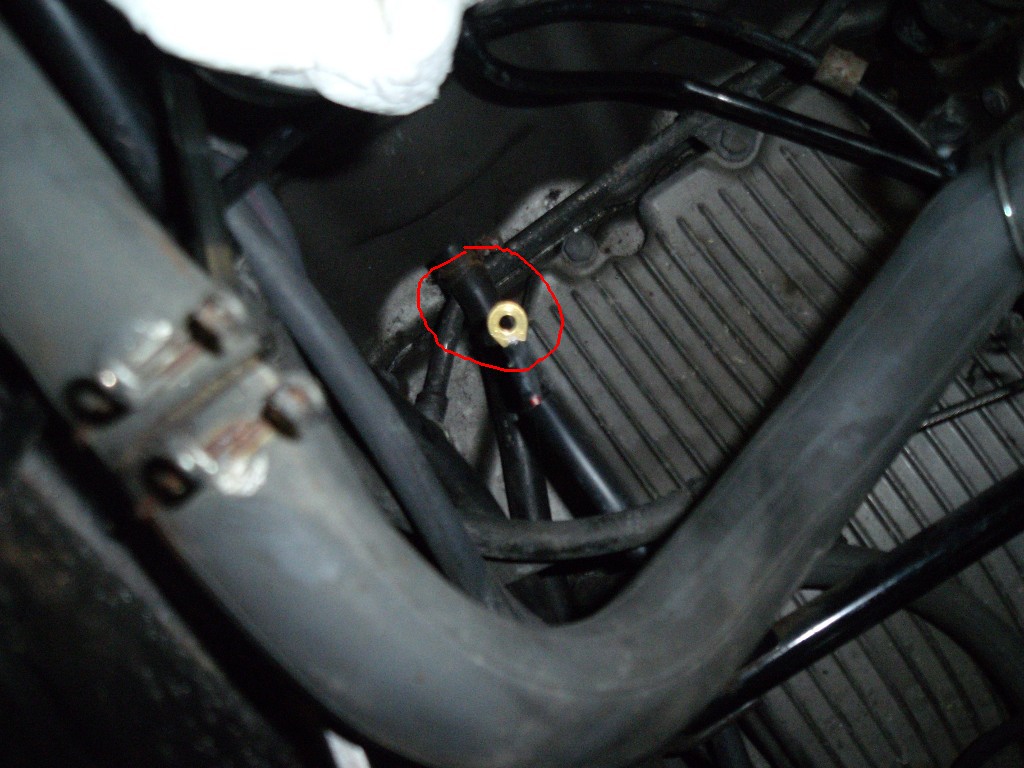
24. Remove the banjo bolt from the left side of the bike and replace it with the oil pressure switch (you may need to loosen the engine mounting bolts (circled) to give you enough room to work.
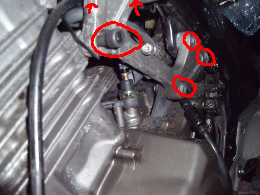
OK now the difficult bit, the oil pressure switch needs to be torqued to 21Nm / 15.49 ft/lb, but you can't get a socket on the switch to do this. A 22mm crowsfoot wrench will fit quite nicely. But it extends the length of your torque wrench by an inch or so, so we need to do a calculation.
My torque wrench is 9 inches long and my crowsfoot adapter is 1 inch long :
15.49 ft /lb x 9" / 9" + 1" = 13.941 ft/lb (so 13.9 ft / lb on torque wrench with crows foot on equals 15.49 ft /lb without)
It's all explained here:
http://www.cditorque...e_adapters.html
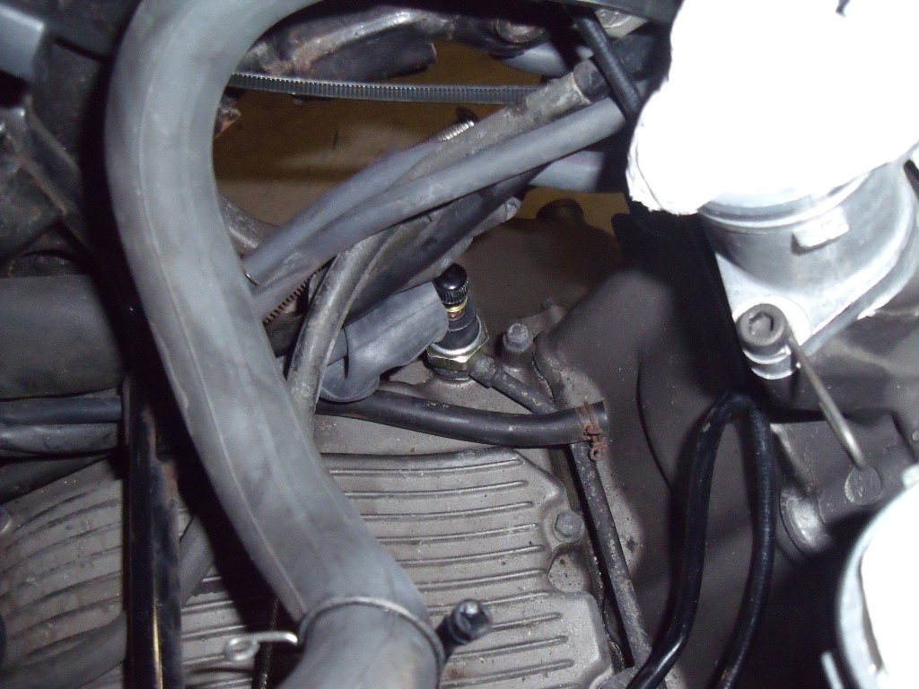
25. The oil switch installed
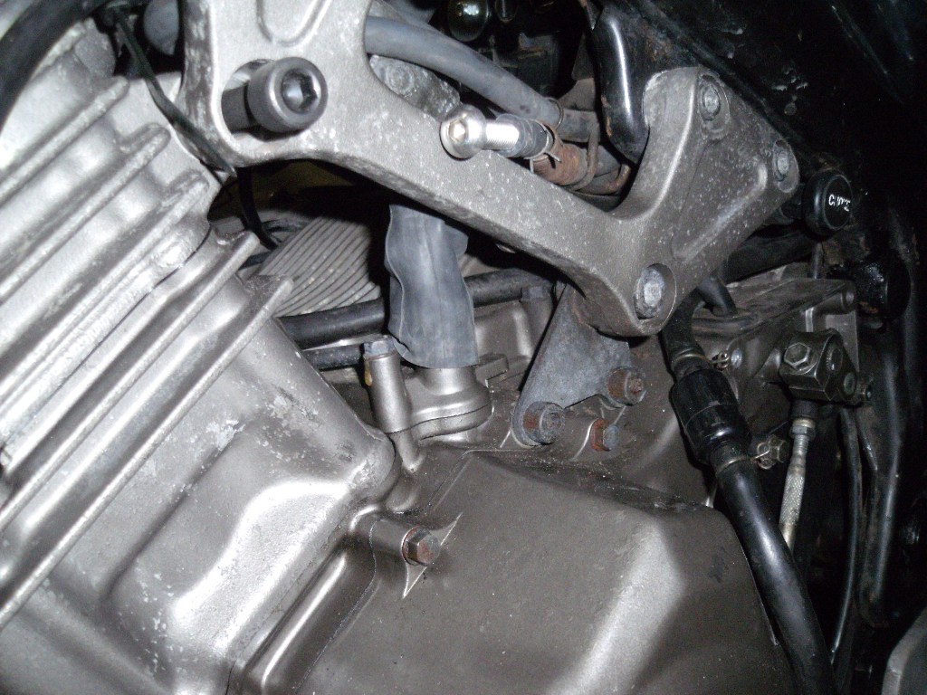
26. Add a short length of mountain bike inner tube for an effective cover / boot.
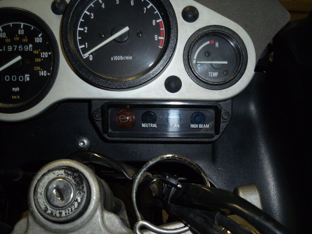
27. The instruments installed on the bike
28. Wiring diagram
Edited by hammerman, 03 May 2010 - 06:44 pm.


